Original paper
UCMCTrack: Multi-Object Tracking with Uniform Camera Motion Compensation
- Publication
- AAAI 2024Conference
- First submitted to arXiv
- arXiv:2312.08952
Cite this paper · BibTeX
The citation identifies the linked source version. It cites the original paper and its authors.
@misc{multiobjecttrackingucmctrack2023,
  title = {{UCMCTrack: Multi-Object Tracking with Uniform Camera Motion Compensation}},
  author = {Kefu Yi and Kai Luo and Xiaolei Luo and Jiangui Huang and Hao Wu and Rongdong Hu and Wei Hao},
  year = {2023},
  eprint = {2312.08952},
  archivePrefix = {arXiv},
  url = {https://arxiv.org/abs/2312.08952}
}
What trackers that rely on motion alone fear most is a moving camera.
The person is standing perfectly still, but the camera pans and their position in the frame jumps a long way. The box the Kalman filter predicts no longer lines up with the newly detected box, IoU drops to 0, and the track breaks.
There are two common fixes. One is to add appearance features; the other is camera motion compensation (CMC), which estimates how the camera moved in every frame and then corrects the track positions back. BoT-SORT, StrongSORT and Deep OC-SORT all do this. Both work, but both cost extra computation. Per-frame camera motion compensation has to extract keypoints, compute optical flow or run image registration on every frame, which gets heavy once the video resolution goes up.
Kefu Yi, Kai Luo, Wei Hao and colleagues at Changsha University of Science and Technology propose UCMCTrack, which comes at it from a different angle. Rather than tracking in the image, project each person back onto the ground and track them there; treat camera shake as noise in the motion model. A whole video uses a single set of fixed compensation parameters, with nothing computed frame by frame.
Defining the problem
The authors want to know whether a tracker can use motion cues alone, hold up when the camera moves, and still skip per-frame camera motion compensation.
In their view, the trouble lies with IoU and the image plane.
IoU is the most common association distance, but as soon as two boxes don't overlap, it's 0. Camera shake, a low sampling rate and fast-moving targets can all pull the predicted box and the detection box completely apart. Refinements such as GIoU, DIoU and C-BIoU give non-overlapping boxes a score too, but they are all still computed on the image plane.
Positions on the image plane have the camera's motion and perspective distortion mixed into them. For the same single step forward, a person near the camera moves a lot in the frame and a person far away moves only a little. People actually walk on the ground, so truly regular motion should only show up on the ground.
SparseTrack uses estimated pseudo-depth, and Quo Vadis projects positions onto a bird's-eye view to compute distances. Both took a step in this direction, but they still work alongside IoU and don't deal with the uncertainty the projection introduces.
Solving the problem

UCMCTrack is still detect-then-associate and uses motion cues only. What it changes is where the motion model is built, which distance is used for matching, and how camera shake is handled.
Building the motion model on the ground
Take the midpoint of the bottom edge of a person's detection box, and you have roughly where their feet touch the ground. Using the camera's intrinsic and extrinsic parameters, this point is projected from image coordinates to ground coordinates :
is the projection matrix formed from the camera's intrinsics and extrinsics, and is a scale factor.
The Kalman filter runs right on the ground, with a state of only ground position and velocity, , under the simplest constant-velocity model. Unlike the SORT family, which tracks a box's center, area and aspect ratio, it ignores box size entirely.
Once you project, project the error too
The detector's error arises in the image. The authors assume the error in the image is independent in the two directions and proportional in size to the box's width and height:
is the detection noise coefficient, and and are the detection box's width and height.
Projected onto the ground, this error is no longer independent in the two directions. With a first-order approximation of the projection, the error covariance on the ground is
is built from elements of the inverse of the projection matrix and from the ground position. isn't diagonal, so the error on the ground is strongly correlated between the and directions; the authors call this the Correlated Measurement Distribution (CMD).
This makes intuitive sense. When the camera looks down at an angle from above, a person who is off by a few pixels up or down in the frame may, once projected onto the ground, be off by a long way forward or backward along the line of sight. So the uncertainty on the ground is a tilted ellipse stretched along the line of sight, not a circle.
Replacing IoU with the Mahalanobis distance
With a prediction on the ground and a measurement that carries uncertainty, matching uses the Mahalanobis distance. The authors call it the Mapped Mahalanobis Distance (MMD), computed in three steps:
- Residual: , where is the measurement projected onto the ground and is the state predicted by the Kalman filter.
- Covariance of the residual: , where is the predicted covariance.
- Normalized Mahalanobis distance:
The first term is the ordinary Mahalanobis distance. A residual in a direction of high uncertainty costs little, while one in a direction of low uncertainty costs a lot. The second term, , brings the uncertainty itself into the score. The larger the uncertainty, the higher the distance's baseline, so a very vague measurement can't get matched easily just because "anything is possible."
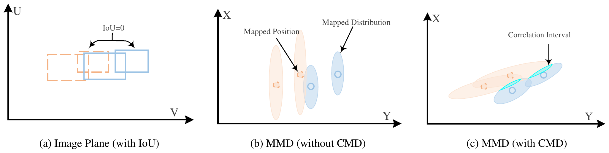
The figure puts the three cases side by side. (a) The two sets of boxes in the image don't overlap, and IoU is no help at all. (b) The distance moves to the ground, but if the error is treated as independent in the two directions, the ellipses are all upright, and the closest one turns out to be the wrong one. (c) With the correlated measurement distribution, the ellipses tilt along the real direction of uncertainty, and only then does the correct matching emerge.
Treating camera shake as noise
Last comes the camera's motion. Instead of estimating how the camera moves in every frame, the authors treat it as a source of noise that causes acceleration. Within a time interval , an unknown acceleration changes the position and the velocity by
Write this as a matrix , and the Kalman filter's process noise covariance is
and are called process compensation factors, and they absorb the motion noise caused by camera tilt and rotation respectively. With the process noise enlarged, the Kalman filter trusts new measurements more and tolerates a larger deviation in its prediction, so the displacement from a jolt of the camera won't break the track.
The two factors stay fixed throughout a video, and that's what "Uniform Camera Motion Compensation" in the title means. Compared with per-frame camera motion compensation, it needs no image processing at all. The authors state that, given the detections, UCMCTrack can process over 1,000 frames per second on a single CPU.
The rest of the pipeline is the same as SORT. The Hungarian algorithm does the matching; unmatched tracks accumulate lost time and are deleted once it passes a threshold; unmatched detections with high enough confidence start new tracks. The whole method uses neither IoU nor appearance features.
Where the camera parameters come from
Projecting points onto the ground requires the camera's intrinsics and extrinsics. KITTI provides them, but MOT17, MOT20 and DanceTrack don't, so the authors estimated them by hand.
The official code comes with an estimation tool. The user adjusts three rotation angles, the focal length and the translation by hand until a virtual ground grid drawn over the frame lines up with the ground in the image. The README also explains that parameters estimated this way may not be very precise, but are good enough for UCMCTrack.
Discussion
Detections all reuse ByteTrack's public YOLOX weights, except on KITTI, which uses PermaTrack's detections. UCMCTrack+ is the version that additionally applies ECC image registration, the same approach StrongSORT takes.
Main results
| Method | MOT17 HOTA | MOT17 IDF1 | DanceTrack HOTA | DanceTrack AssA |
|---|---|---|---|---|
| ByteTrack | 63.1 | 77.3 | 47.3 | 31.4 |
| OC-SORT | 63.2 | 77.5 | 55.1 | 40.4 |
| C-BIoU | 64.1 | 79.7 | 60.6 | 45.4 |
| SparseTrack | 65.1 | 80.1 | 55.5 | 39.1 |
| BoT-SORT* | 65.0 | 80.2 | — | — |
| Deep OC-SORT* | 64.9 | 80.6 | 61.3 | 45.8 |
| UCMCTrack | 64.3 | 79.0 | 63.4 | 51.1 |
| UCMCTrack+ | 65.8 | 81.1 | 63.6 | 51.3 |
Compiled from Tables 1 and 2 of the paper, test sets; methods marked * also use appearance features.
- MOT17: Without image registration, UCMCTrack scores 64.3, about the same as the other pure-motion methods; with it, UCMCTrack+ reaches 65.8, higher than BoT-SORT and Deep OC-SORT, which use appearance features.
- DanceTrack: The gap is wider. UCMCTrack's HOTA is 63.4, 2.8 above C-BIoU, and AssA, which measures association, goes from 45.4 to 51.1. A motion model that relies on position alone beats Deep OC-SORT, appearance and all, on dancers.
- MOT20: UCMCTrack scores 62.8, tying MotionTrack, slightly below SparseTrack's 63.4 and also below Deep OC-SORT (63.9), which uses appearance. Image registration makes no difference here, most likely because MOT20's cameras are fixed to begin with.
- KITTI: This is a 10 FPS driving dataset whose camera moves with the car. UCMCTrack's car HOTA is 77.1, above OC-SORT's 76.5; but UCMCTrack+, with image registration, actually drops to 74.2. The authors suspect the image registration parameters were estimated inaccurately.
What each part contributes
The ablation takes ByteTrack as the baseline and swaps parts in step by step on the MOT17 and DanceTrack validation sets:
| Setup | MOT17 HOTA | MOT17 IDF1 | DanceTrack HOTA | DanceTrack IDF1 |
|---|---|---|---|---|
| ByteTrack (IoU) | 68.4 | 77.1 | 47.9 | 47.3 |
| Swap in MMD | 68.1 | 75.9 | 46.3 | 43.8 |
| + CMD | 70.4 | 79.7 | 55.1 | 53.9 |
| + noise compensation | 72.0 | 82.2 | 60.4 | 62.6 |
Compiled from Table 4 of the paper, validation sets.
- Merely swapping IoU for the Mahalanobis distance makes things worse. The authors' explanation is that IoU takes both position and box height into account, while MMD looks only at a single point on the ground. They also mention that height information could be added to MMD in the future.
- Adding the correlated measurement distribution takes it past IoU. On DanceTrack it jumps from 46.3 to 55.1, a gain of nearly 9 points. Only when the shape of the error is projected correctly does distance on the ground become meaningful.
- Process noise compensation adds another big step. MOT17 gains 1.6 points, DanceTrack 5.3, and DanceTrack's IDF1 a full 8.7.
On point 3, the authors themselves say that most DanceTrack videos have no noticeable change of viewpoint; the camera is almost fixed. So what is process noise compensation compensating for here? This note's guess is that enlarging the process noise makes the Kalman filter more willing to trust new measurements and tolerate larger prediction errors, so what it absorbs is mostly the deviation caused by dancers suddenly changing direction or speed, not camera shake. Seen this way, it is dealing with the same problem as OC-SORT's fixes to the Kalman filter and C-BIoU's enlarged boxes.
Is per-frame compensation still worth doing?
| Setup | MOT17 HOTA | DanceTrack HOTA |
|---|---|---|
| ByteTrack | 68.4 | 47.9 |
| ByteTrack + per-frame CMC | 71.0 | 47.6 |
| UCMCTrack | 72.0 | 60.4 |
| UCMCTrack + per-frame CMC | 73.0 | 59.2 |
Compiled from Table 5 of the paper, validation sets.
On MOT17, UCMCTrack alone beats "ByteTrack plus per-frame compensation," and stacking the two adds 1 more point. On DanceTrack, though, adding per-frame compensation makes both methods worse. The authors' explanation is that DanceTrack's camera barely moves, so image registration ends up introducing small shifts among people who overlap, and they get matched to the wrong tracks.
The compensation factor depends on the scene
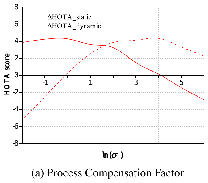
The authors split the MOT17 validation set into a fixed-camera group and a moving-camera group and swept the compensation factor. The two curves are almost mirror images. For fixed-camera videos, a smallish factor works best, and too large a one ends up worse than the baseline; for moving-camera videos, the factor has to be as large as about , and too small a one is 5 points worse than the baseline.
So "uniform" means fixed within one video; different videos still need their own settings. As for the detection noise coefficient , 0.05 works best, and anywhere between 0.04 and 0.1 makes little difference.
What if the camera parameters are wrong?
The camera parameters are estimated by hand, so some error is unavoidable. The authors added error to each of the three rotation axes of the extrinsics in turn. Yaw error, around the vertical axis, has little effect, because it hardly deforms the estimated ground; large errors on the other two axes visibly warp the ground, and performance drops with it. When that happens, the parameters have to be readjusted until the estimated ground lines up with the real one.
This is also the most practical hurdle in using the method. Quite a few issues on the official repository ask how to estimate the camera parameters, and whether they can be estimated fully automatically.
Conclusion
UCMCTrack moves multi-object tracking from the image plane back onto the ground. The midpoint of each detection box's bottom edge is projected onto the ground, the error is projected along with it into a tilted ellipse, and the Mahalanobis distance replaces IoU; camera shake is treated as the Kalman filter's process noise, with one set of parameters per video. With no appearance and no per-frame image registration, it catches up with, and even overtakes, methods that use appearance features on both MOT17 and DanceTrack.
The price is that it needs camera parameters, which most public datasets don't provide, so they have to be estimated by hand. The authors also acknowledge that the method assumes everyone stands on the same plane, which no longer holds in scenes such as stairs, grandstands and slopes.
What a tracker sees in the image is a projected world. Put it back on the ground, and a lot of motion that looks irregular turns out to be an illusion created by perspective and camera shake.